croak2 belongs to the class of antiferromagnets with a rutile-type crystallographic lattice27described by P42/mnm space group. The primitive many-atomic cell forms 11 optical phonon modes28,29: or1g ⊕ or2g ⊕ or2u ⊕ B1g ⊕2B1u ⊕ B2g ⊕3Eu ⊕ Eg. The lowest Raman active phonon mode has B1 g symmetry and is centered at a frequency of pph = 1.96 THz at T = 6 K. It is worth noting that the frequency of this mode remains the same in the external magnetic field up to μ0Hext= 7T.
Co. Rolls2+ ions are aligned along the crystallographic c axis below the Néel temperature of TN= 39 K. In our experiment, we use a 500 µm thick CoF single crystal2 plate cut perpendicular to the c axis. If no magnetic field is applied, there is a frequency-degenerate double antiferromagnetic resonance p0 = 1.14 THz (at 6 K). By applying an external magnetic field, one breaks the degeneracy of the corresponding magnon mode. For example, if a magnetic field is applied along the c-axis with its value below the spin-flop field threshold of μ0Hext = 14T30the frequencies of the two degenerate magnon modes obey the relation pm = p0 ± γHextwhere γis the gyromagnetic ratio.
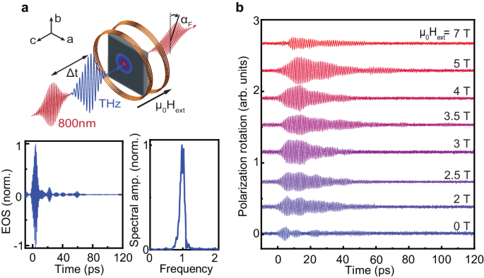
Using the intense, spectrally dense superradiant THz source TELBE, located at the Helmholtz-Zentrum Dresden-Rossendorf31 in combination with external magnetic fields Hext we have the unique ability to selectively pump the magnon by controlling its center frequencypmtuning in Hext at our disposal. This setup allows you to explore the spin-lattice interaction in the vicinity of the Fermi 2 resonance pm = pphby monitoring the phonon response. As shown earlier24as long as both magnon and phonon retain their coherence, they will induce transient optical anisotropy in the initially isotropic (ab) plane of the antiferromagnet and thus modulate different components of the dielectric permittivity32which we track from probe polarization changes24. The experimental geometry and characteristics of the THz pulse are given in Fig. 2a. The THz field strength was estimated to be of the order of 100 kV/cm. THz-induced rotation of the probe polarization is measured in external magnetic fields up to μ0Hext= 7 T is shown in figure 2b. Apparently, the time field signal exhibits clear oscillations that are significantly affected by an external magnetic field. Here, the magnon amplitude dominates from −10 to 70 ps while for the range 70–120 ps, the phonon appears to be exclusively present. In Supplementary Section A, we illustrate our observations with the sinusoidal fitting of the corresponding magnon and phonon oscillations.

or THz pump – IR probe spectroscopy with an external magnetic field applied perpendicular to the sample plane, along the c-axis. THz-induced polarization spin changes of the probes aFare measured by a balanced photodetector. Electro-optical sampling of the THz pulse (nitrogen purge) is shown in both the time and frequency domains. b Time domain data for polarization rotation aF for a series of external magnetic field values measured at T= 6 K.
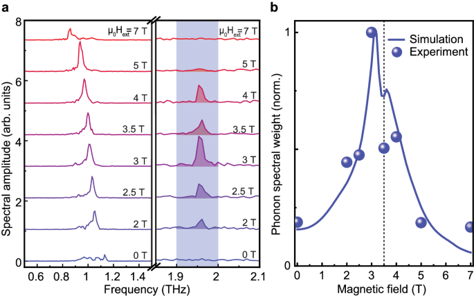
Performing the Fourier transform of the entire time domain range (−10 to 120 ps) in Figs. 3a reveals the presence of frequency-oscillating Magnon response pm and a second peak, distant at B1 gphonon frequency pph. For magnetic fields μ0Hext = 0 T and μ0Hext = 7 T, the THz pump spectrum barely covers the magnon mode and the THz-induced polarization rotation contains a substantial contribution of the spectrally broad forced magnetic response closely following the magnetic field of the THz pulse, see Fig. 2b. Furthermore, no phonon-induced dynamics is observed in these fields, implying that the nonlinear excitation of phonons via the mechanism described in ref. 1 does not play an important role here. Closer to the Fermi resonance for magnetic fields between μ0Hext= 2–5 T, we observe the low-energy magnon branch pmwith its frequency decreasing linearly with the external magnetic field. Surprisingly, Magnon’s strongest climax in μ0Hext= 5 T does not correspond to the strongest phonon peak, revealing complex dynamics in the vicinity of the magnon-phonon Fermi resonance.

or The Fourier transform of the time domain signals in Fig. 2b shown with equidistant displacement near the magnon (left) and phonon (right) resonance frequencies. To compensate for the THz power variation of the TELBE source, the magnon (phonon) spectral amplitude is normalized by the square root of the THz power (THz power). b The phonon spectral weight (blue spheres) extracted as an integral value over the shaded frequency interval at (or). The phonon weight from our numerical calculation is shown as the solid blue line. The vertical dotted line highlights the drop in phonon spectral weight in Hext= 3.5 T for both simulation and experiment. Excluding effects that may also contribute to our signal on the time scale of our THz pump pulse, i.e., the nonlinear electro-optical Kerr effect, we demonstrate even better agreement of experiment and simulation in Supplementary Section A.
The most special feature is observed in μ0Hext= 3.5 T, see Fig. 3a. First, the phonon peak amplitude for dynamics in this magnetic field is significantly reduced relative to the peak amplitude for μ0Hext= 3 T and 4 T. Second, the phonon spectrum at μ0Hext= 3.5 T becomes wider. In fact, this resembles a spectral line splitting reported for purely phononic8 or simply magnonic13 systems under continuous wave pumping in the vicinity of their Fermi resonances. To capture the energy redistribution, we integrate the area under the phonon spectra for different external magnetic fieldsHextover the shaded range of 1.9-2.0 THz and obtain the phonon resonance curve behavior as shown in Figs. 3b. Here, the phonon resonance line is clearly asymmetric with a pronounced drop inμ0Hext= 3.5 T indicating non-trivial magnon-phonon energy exchange. In the next section, we assign this feature to the unique magnon-phonon Fermi resonance standards. Furthermore, we treat magnon and phonon lifetimes and reveal the role of nonlinear coupling constants for raising the system to the strong nonlinear magnon–phonon coupling regime.
To get a better insight into the observed fingerprint of the magnon-phonon Fermi resonance, we undertook a simulation of the signatures of the nonlinear coupled dynamics in the CoF2. Conventionally, antiferromagnetic spins are described in terms of the Néel vector L=M1− M2where the net magnetic moments M1,2were formed by Co2+ ions at the center and corners of the unit cell, respectively33. The movement of B1 gthe phonon is characterized by the phonon coordinateθph. Perturbations from the ground state are represented as L (t) = ( lx(t ), ly(t), L0). here, L0describes the Néel ground state vector. The Fermi resonance symmetry rule implies that B1 gphonon symmetry (x2– y2) should follow the double magnon excitation symmetry. Therefore, the corresponding nonlinear term can be introduced into the Lagrangian as \(\Phi=-\alpha ({l}_{x}^{2}-{l}_{y}^{2}){\theta }_{ph}\)15where arepresents the nonlinear coupling constant between the magnon and phonon subsystems. We assume that the magnetic field of the THz pulse hTHz= ( hx, hy0) is polarized exclusively in the sample plane and solves the Lagrange-Euler equations, taking into account circularly polarized magnon states l±= lx± Thely. The resulting coupled equations can be written as
$$\frac{{d}^{2}{l}_{+}}{d{t}^{2}}+2{\zeta }_{{{{{{{{\rm{m} }}}}}}}}\frac{d{l}_{+}}{dt}+\left({\omega }_{0}^{2}}{\gamma }^{2}{H }_{{{{{{{\rm{ext}}}}}}}}^{2}\right){l}_{+}+2\gamma i{H}_{{{{{ { {{{\rm{ext}}}}}}}}\frac{d{l}_{+}}{dt}=-2\alpha {\theta }_{{{{{{{{{ \ rm{ph}}}}}}}}{l}_{-}+\gamma \frac{d}{dt}({h}_{y}-i{h}_{x}), $$
(1)
$$\frac{{d}^{2}{l}_{-}}{d{t}^{2}}+2{\zeta }_{{{{{{{{\rm{m} }}}}}}}}\frac{d{l}_{-}}{dt}+\left({\omega }_{0}^{2}}{\gamma }^{2}{H }_{{{{{{{\rm{ext}}}}}}}}^{2}\right){l}_{-}-2\gamma i{H}_{{{{{ { {{{\rm{ext}}}}}}}}\frac{d{l}_{-}}{dt}=2\alpha {\theta }_{{{{{{{{\ rm{ ph}}}}}}}}{l}_{+}+\gamma \frac{d}{dt}({h}_{y}+i{h}_{x}),$ $
(2)
$$\frac{{d}^{2}{\theta }_{ph}}{d{t}^{2}}+2{\zeta }_{{{{{{{\rm{ph } }}}}}}}}\frac{d{\theta }_{ph}}{dt}+{\omega }_{{{{{{{{\rm{ph}}}}}}}} } }^{2}{\theta }_{{{{{{{\rm{ph}}}}}}}}=-\alpha \left({l}_{+}^{2} +{l }_{-}^{2}\right),$$
(3)
where ωThe= 2 πpThe and Gilbert damping factors ζThe withThe= “m” or “ph” account for the magnon or phonon subsystem, respectively. The second term on the right-hand side of Ex. (1)–(2) represents the linear Zeeman torque34, while the nonlinear coupling can be introduced in Eqs. (1)–(3) as the derivative of Φ in the corresponding order parameter. These terms represent the nonlinear mutual perturbation of the magnon (phonon) subsystem by the phonon (magnon) subsystem. The experimental THz pulse waveform measured by electro-optical sampling (see Fig. 2a) is introduced as the driving force in our simulation. The derivation of Eqs. (1)–(3) is given in Supplementary Material, Section B.
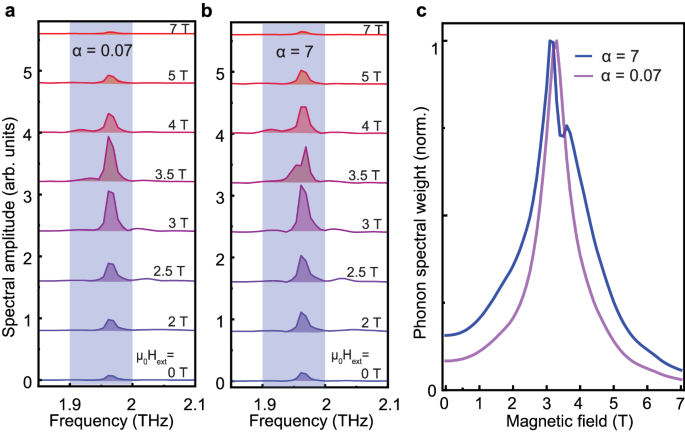
In Fig. 4a,b, the simulated phonon spectra are shown for the external magnetic fields as applied in our experiment. Here, panel (a) corresponds to the weak coupling case witha= 0.07, while panel (b) represents the case of strong coupling witha= 7. A drastic change in the spectra for the magnetic fields ofμ0Hext= 3, 3.5 and 4 T can be seen, highlighting the role of the Fermi resonance. In the weak coupling regime of Fig. 4a, the spectrum contains no splitting and the peak amplitude has only a single near maximumμ0Hext= 3.5 T. The corresponding phonon weight shown in panel (c) is also symmetric. In the strong coupling regime (see Fig. 4b), atμ0Hext= 3.5 T a splitting of the phonon line is observed resulting in a decrease in the phonon weight. Moreover, the absolute peak of the phonon weight is shifted to 3 T. These features are well captured by our experimental data set (see Fig. 3) showing good agreement with our model. We elaborate on the clear effect of our simulation parameters in Supplementary Material, Section C.

or The Fourier transform was centered around the phonon resonance for the case of weak coupling witha= 0.07. b The Fourier transform was centered around the phonon resonance for the case of strong coupling witha= 7.cThe phonon weight extracted as an integral value in the shaded frequency region of 1.9–2.0 THz for the weak coupling case (purple line) and the strong coupling case (blue line), respectively. Noticeable difference for FFT line shapes in the range ofμ0Hext= 3–4 T ( or,b) and the emitted phonon weight (c) clearly highlights the mutual coupling between the two magnons and the phonon state.
#Magnonphonon #Fermi #resonance #antiferromagnetic #CoF2 #Nature #Communications
Image Source : www.nature.com
